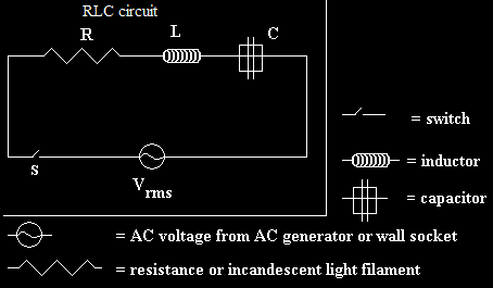
In this article we will learn about an electrical circuit where an AC voltage is applied across an inductor, a capacitor and a resistor connected in series.

Consider the circuit shown above. Here, we have an inductor, a resistor and a capacitor connected through a series connection across an AC voltage source given by V. Here, the voltage is sinusoidal in nature and is given by the equation,
Here, vm is the amplitude of the voltage and ω is the frequency.
If q is the charge on the capacitor and i the current at time t, we have, from Kirchhoff’s loop rule:

Here, q is the charge held by the capacitor, I is the current passing through the circuit, R is the resistance of the resistor and C is the capacitance of the capacitor. In order to determine the instantaneous current or the phase of the relationship, we will follow the analytical analysis of the circuit.
Analytical solution
As i
, we can write
Hence, writing the voltage equation in terms of the charge q through the circuit, we can write,

The above equation can be considered analogous to the equation of a forced, damped oscillator. In order to solve the equation, we assume a solution given by,
So,

And

Substituting these values in the voltage equation, we can write,
Here, we have substituted the value of Xc and XL by Xc = 1/ωC and XL = ω L.
As we know,
hence substituting this value in the above equation, we get,

Now, let

So we can say,

Now, comparing the two sides of the equation, we can write,
And,

Hence, the equation for current in the circuit can be given as,
0 comments :
Post a Comment