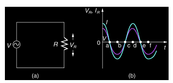
In this section, we will deal with an electric circuit, where an AC voltage is applied across a resistor. Let us consider the circuit shown below. We have a resistor and an AC voltage V, represented by the symbol ~, that produces a potential difference across its terminals that varies sinusoidally. Here, the potential difference or the ac voltage can be given as,
Here, vm is the amplitude of the oscillating potential difference and the angular frequency is given by ω.

The current through the resistor due to the present voltage source can be calculated using the Kirchhoff’s loop rule, as under,
Here, using this equation, we can write,
Or,
Here, R is the resistance of the given resistor and hence we can write,
From the Ohm’s law, we can write,
as it works equally well for AC voltages and DC voltages. We saw that the voltage across the resistor and the current passing through it are both sinusoidal quantities and are represented by the graph shown in the figure above. Both the quantities are in-phase with each other.
The average value of power over the complete cycle is given as,
Here the quantities im and R are constants and hence, the above equation is evaluated as,
Using trigonometry, we have sin2ωt=12(1−cos2ωt) sin2ωt=12(1−cos2ωt) cos2ωt=0
Thus we can also write,
It is important to note that the AC power can also be expressed as DC power if we denote the current in terms of the effective current or the root mean square current.
0 comments :
Post a Comment